PWM DC speed regulating electrical appliance
2020/12/04 11:46:12
This series of regulated power supplies adopts pulse width modulation technology and is designed and produced using advanced switching devices. It has a small size, operates without noise, high efficiency, and advanced short-circuit protection function (which can ensure frequent forward and reverse rotation of the motor). The armature output voltage is stable, and its armature voltage can be continuously adjusted from zero to rated value, making motor speed regulation convenient. Due to its high operating frequency, this series of power supplies ensures that the motor can operate stably at low speeds (i.e. without crawling), making it an ideal replacement for thyristor speed control power supplies.
■ Usage conditions
*The altitude shall not exceed 4000m; the usage environment shall be free of conductive dust and various corrosive gases; *Environmental temperature; -20 ° C~+40 ° C; * Place without explosion hazard and without severe vibration and impact * Relative humidity ≤ 85%; *Installed indoors with good ventilation.
*Allow the voltage fluctuation range of the AC power grid to be 160V-250V;
■ Safety operation precautions
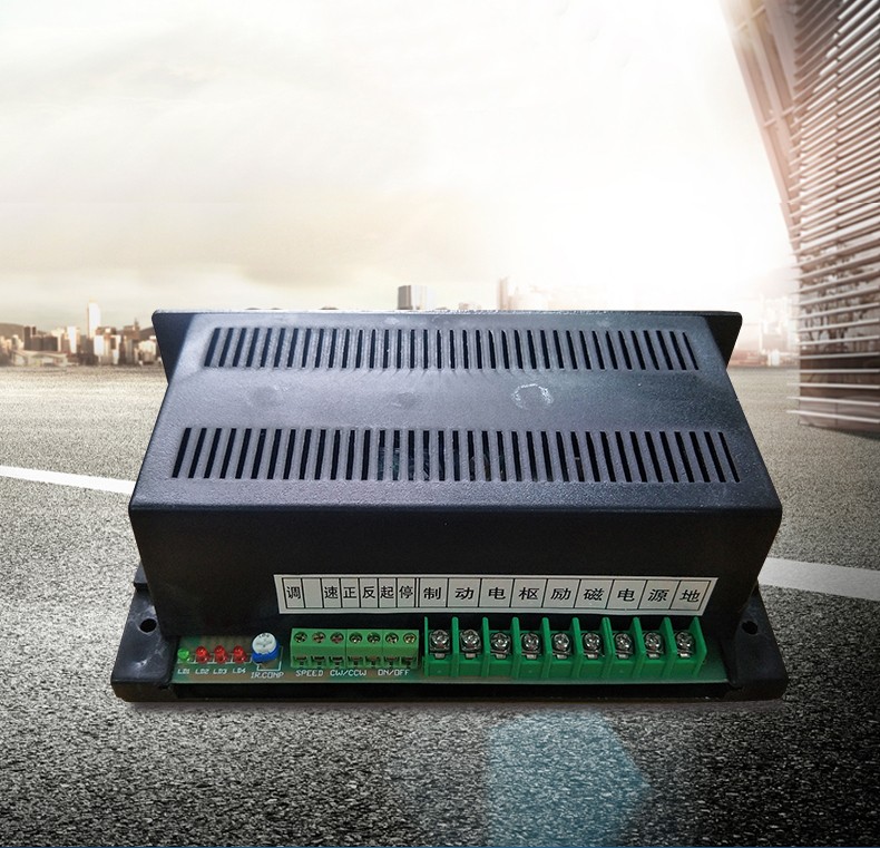
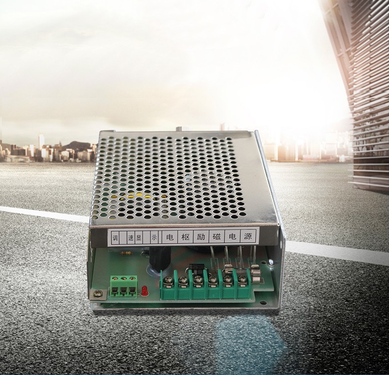
1. The speed control SPEED uses a 4K7 potentiometer, and the voltage withstand strength between the potentiometer terminal and the potentiometer housing is required to be no less than 500V. ON/OFF, CW/CCW, and potentiometers should be connected to the speed controller with well insulated wires. 0N/OFF is used to control the start and stop of the motor, and CW/CCW is used for motor forward and reverse control.
2. When connecting with an electromagnetic motor, please distinguish between the armature and excitation of the motor, and correctly connect them to the corresponding terminals of the governor. Do not connect them in reverse, otherwise it will damage the governor. When connecting with a permanent magnet motor, please directly connect the motor to the armature port of the governor, and do not use the excitation port when it is empty.
3. This speed controller needs to adjust the IR.C0MP potentiometer appropriately according to the power of the motor it is equipped with. The specific adjustment method is as follows: first, turn the IR.COMP potentiometer counterclockwise to the bottom, start the speed controller, and let the motor run at low speed. Then adjust the IR.C0MP potentiometer clockwise, and observe LED4 while adjusting the speed. If LED4 flashes, please turn the IR.COMP counterclockwise until LED4_ stops flashing, and the adjustment will be completed.
4. To change the direction of the motor, simply swap the A+and A - ports on the armature of the speed controller. If the motor needs to reverse direction during operation, please choose one with an H-type. Therefore, the speed controller of this model already has a reversing relay and an energy consumption brake relay inside, which can automatically reverse direction through a program. During the reversing process, the relay and motor have no sparks.
5. The size of the braking resistor connected to the H-type should be selected according to the braking time, generally ranging from tens of ohms to tens of ohms. The braking time needs to be short, and the resistance value should be small. Conversely, the resistance should be larger, and its value should not be less than 10 ohms as much as possible. The resistance power should be greater than 10W. (Note: Do not directly connect the resistor to the terminal block, as the resistor heats up severely and may melt the terminal block.)